Digital waveguide modeling of musical instruments is one of the most popular sound synthesis techniques at present. This methodology has been mainly developed by Smith [Smith, 1992]. Digital waveguide modeling is well suited to synthesis of wind and string instruments, although the same principles have recently been applied to the piano and percussion instruments as well.
Digital waveguide synthesis of the flute has been a target of active research during the recent years. The first version of a real-time digital waveguide flute model was introduced by Karjalainen et al. [Karjalainen, 1991] and Välimäki et al. [VŠlimŠki, 1992]. Cook has implemented a simplified version of this model [Cook, 1992]. Similar principles for simulating the air reed mechanism of the flute had been used by McIntyre et al. [McIntyre, 1983] and Wawrzynek [Wawrzynek, 1989]. More recently also Coltman [Coltman, 1992] has reported on a flute simulation model. Newest developments in flute modeling include the works of Chafe [Chafe, 1995] and Cook [Cook, 1995]. A more detailed and physically accurate flute model could be constructed based on recent research by Verge [Verge, 1995]. Other research work on flute synthesis using a time-domain model include [Magalotti, 1995a], [Magalotti, 1995b], and [Agull—, 1995].
So far, many implementations have failed to produce realistic flute sound that could be controlled using the same techniques that are used to play a real flute. One of the major problems has been the note transition. Changing the length of the delay lines of the waveguide flute changes the pitch but produces an audible ëclickí when the internal state of the model abruptly changes. On the other hand, changing the length of the delay lines gradually changes the state smoothly but produces an undesirable pitch-bend effect.
A solution to these problems was introduced in [VŠlimŠki, 1993b] and [VŠlimŠki, 1995]. The finger holes that are used to control the pitch in a flute must be incorporated into the model. Their position is adjusted using interpolation techniques, which are implemented as fractional delay filters [Laakso, 1996]. Our implementation uses fractional delay filters that match the function, location and size of the finger holes of a real flute.
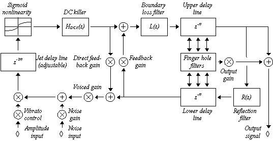
The overall structure of the new flute model is nearly the same as that described in [VŠlimŠki, 1992]. This version however includes multiple simultaneously functioning finger holes. The signal flowgraph of the new, improved flute model is illustrated in Figure 1.
- Boundary Loss Filter
The boundary loss filter in [VŠlimŠki, 1992] has been moved from the end of the upper delay line. When placed before the upper delay line, it now affects also the upper delay line finger hole filter inputs. As explained in [VŠlimŠki, 1992], the boundary loss filter models signal losses that occur when sound waves propagate along the flute main tube. For the sake of efficiency, all loss filtering is realized by one filter, and as long as there is only one signal output, this is perfectly legal [Smith, 1992]. With finger hole filters, a more accurate, but computationally much more expensive solution would be to distribute the loss filtering among several "smaller" loss filters, placed between signal outputs.
- Modeling an Open Finger Hole
Each open finger hole is implemented as a three-port junction. It is assumed that a finger hole is a short side-branch in the bore of the tube. The acoustic impedance of the side-branch is simulated with a first-order IIR filter as described in [VŠlimŠki, 1993b] and [VŠlimŠki, 1995].
The location of the finger hole must be very carefully adjusted. This is achieved by using interpolation techniques. The input signal to the finger hole model is obtained using some bandlimited interpolation method (we use Lagrange interpolation). The output signal of the finger hole model must be injected equally carefully back into noninteger points of the delay line. Deinterpolation [VŠlimŠki, 1993a] is a new signal processing method that performs this operation. Deinterpolation may be implemented with an FIR filter which has the same coefficients as a corresponding interpolation filter [VŠlimŠki, 1995].

Figure 1: Block diagram of the new waveguide flute model
Two different implementations of the flute model have been built: one with Matlab for easy testing and analysis and another with C++ for high performance. Only the Matlab version is described here since it is simpler and easier to explain. The complete source code for the Matlab version may be obtained from [Hänninen, 1995].
- Multiple Finger Holes
If properly arranged, the finger hole filtering and the interpolation and deinterpolation operations can be carried out with just a few matrix and vector operations. For example, a delay line of length N can be conveniently expressed as a vector with N components.
We first define a sparse COEFFS matrix that stores the Lagrange interpolation coefficients for fractional delay filters. COEFFS is a N M matrix, where N is the length of the delay line and M is the number of finger holes. Each column of the COEFFS matrix holds Lagrange coefficients for one fractional delay filter. The coefficient groups are padded with zeros, and the placement of coefficients within columns defines the integer part of each delay. For example, let us assume that N = 80, M = 2, the order of the fractional delay filters is 3, and the finger holes are located at positions 40.3 and 60.1. The matrix COEFFS then becomes:
 (1)
(1)
where subscript T denotes matrix transposition. After COEFFS has been initialized, the input signals for all finger hole models can be computed with a single instruction:
 (2)
(2)
UPPER and LOWER are both 1 N vectors and represent the upper and lower delay lines of the waveguide model, respectively. The LOWER delay line flows in the opposite direction than the UPPER delay line, and the order of elements in LOWER is therefore reversed. VENTINPUT is a 1 M row vector that contains the fractionally delayed samples for the M finger hole models.
The finger hole filters are approximated with first-order IIR filters ([VŠlimŠki, 1993b] and [VŠlimŠki, 1995]), and the outputs of the M filters are collected into a 1 M vector:
 (3)
(3)
AR and BR are finger hole filter parameters and VENTOUTPUT on the right side of the equation holds the previous VENTOUTPUT values. AR and BR may be scalars if the parameters are the same for all finger hole filters, or vectors if the parameters vary.
The values in VENTOUTPUT are distributed back to the upper and lower delay lines using deinterpolation. The same Lagrange interpolation coefficients that were used to extract the fractionally delayed samples are used to insert them back into the delay lines VŠlimŠki, 1995. Reversing the interpolation process, we first construct a deinterpolation vector:
 (4)
(4)
This yields a 1 N vector where each element is the sum over all finger hole filter outputs, weighted by the appropriate fractional delay filter coefficients. These values are then added to the upper and lower delay lines, finishing the deinterpolation operation:
 (5)
(5)
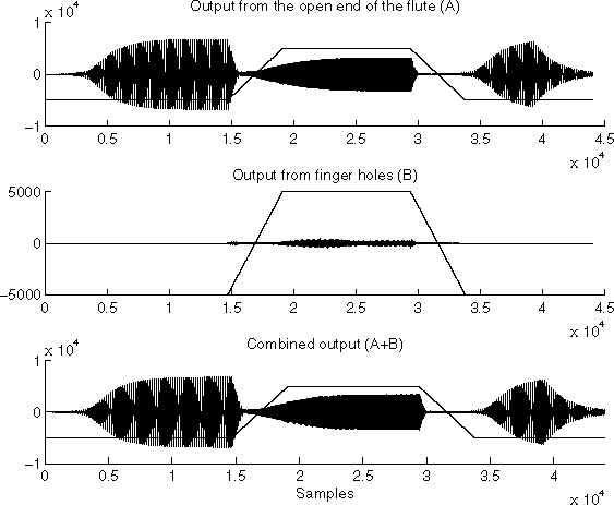
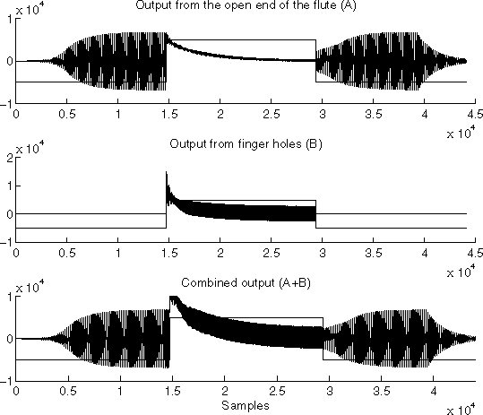
The proposed flute model produces a convincing flute-like sound that changes pitch smoothly when the finger holes are opened and closed. Nevertheless, this requires that the finger holes themselves are operated smoothly. This is realistic since the finger holes of a real flute do not open or close infinitely fast. Any abrupt change in the values of the finger hole parameters creates a severe discontinuation to the internal state of the model which produces an audible click. Adjusting the parameters gradually removes this effect.

Figure 2. Smooth finger hole operation
Below we give two examples of the behaviour of the Matlab version of the flute model Hänninen, 1995. Both tests were run using the configurable parameter set shown in Table 1. The only difference between these examples is how the finger hole parameters are operated: in Figure 2, they are changed smoothly, in Figure 3, infinitely fast. The continuous line in the figures shows the state of the finger holes.
A real flute is controlled with finger holes and input air flow. The air flow control is brought into the flute model by controlling the amplitude of the noise input and the length of the jet delay line. The control over the jet delay line length corresponds mainly to the angle in which a flutist blows air into a mouth piece. The blowing technique has the important function of controlling the overblowing effect of the flute.
When no overblowing is in effect and all finger holes are closed, the jet line length is equal to the sum of upper and lower line lengths. By halving the length of the jet line, the model starts to overblow, producing one octave higher pitch (the fundamental frequency is doubled). Halving the jet line length again raises the pitch a fifth more, etc.
It is interesting to note that the exact jet line length required to reach a certain note and overblow level depends on the current note and overblowing level of the flute model. The current resonator equilibrium state affects the requirements to reach a new equilibrium state, just like with a real flute. Although this does not usually require any conscious effort, a real flutist must also learn the proper blowing techniques for every possible transition from one note to another. With our flute model, the jet line length must be equally carefully adjusted to produce the expected sounds.
| Flute length: | 80 | Sample rate: | 44.1 KHz |
| # of holes: | 2 | Sim. time: | 1 s |
| Pos. of FH1: | 40.3 | Interp. Ord: | 2 |
| Pos. of FH2: | 60.1 | RAND seed: | 1 |

Figure 3. Infinitely fast finger hole operation
Our complete implementation of the proposed model includes the full finger hole set of a flute. Measuring the location and sizes of the finger holes from a real flute and converting them to finger hole parameters produces suprisingly good result. Just like when designing and building a flute, many finger hole configurations fail to produce any sound at all. Therefore, finding a set of 15 finger holes that responds correctly to flute fingering combinations is a success in itself. Unfortunately, fine-tuning the numerous parameters of the flute model is a difficult task. An interesting possibility to adjust the parameters of the linear part (tube) of the flute would be to measure the delay and filter characteristics needed for each finger hole, following the guidelines proposed by Karjalainen et al. [Karjalainen, 1995]. One more alternative way to adjust the parameter values would be to use an automatic learning system, such as a genetic algorithm [Vuori, 1993].